Looking ahead to Round 13 of the 2019 Formula One season in Belgium, as F1 returns from the summer break
- Toto Talks Belgium
- Featured this Week: the Internal Combustion Engine
- Stat Attack: Belgium and Beyond
Toto Talks Belgium
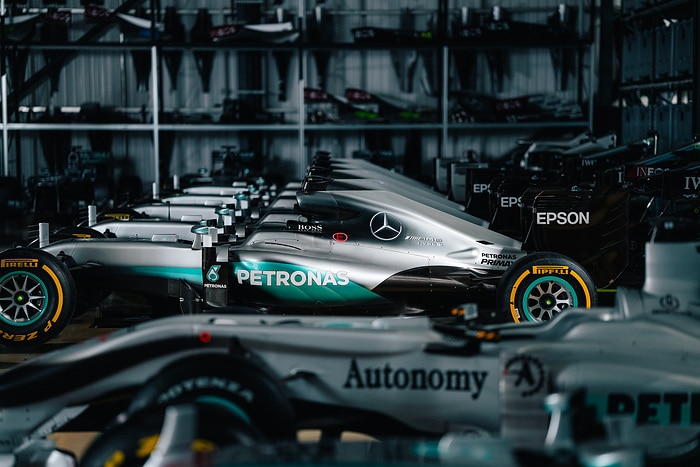
Summer shutdown was a welcome break after some very busy weeks in July and early August, but now we’re excited to go racing again. While the majority of our colleagues in Brackley had the chance to recharge their batteries for the second half of the season, other team members were carrying the baton over the past weeks. Our team members in Brixworth worked straight through the F1 summer break to improve the performance and reliability of our Power Unit; in Brackley, we used the relatively quite days to do some work on our factory. It’s great to come back from the summer break knowing that part of the team was still pushing flat out and we are grateful to our colleagues who kept the ball rolling while we were out of office.
We’re leading in both championships, but it doesn’t feel that way. In the last few years, we saw teams perform very strongly after summer shutdown, so we now we need to keep pushing. In that respect, we’re approaching the start to the second half of 2019 more like the start to a completely new season – once again we need to make sure that we leave no room for error and keep raising the bar.
We’re very excited for the upcoming months with historic races like Belgium and Italy followed by the Singapore night race and many other fantastic events. The next stop takes us to Spa, one of the most iconic circuits on the calendar. Finding the right set-up is tricky because the track has a challenging mix of long straights, a wide range of corner speeds and also considerable elevation changes. The weather can also be somewhat unpredictable in the Ardennes which can make the sessions very interesting. We’re looking forward to the fight.
Featured this Week: the Internal Combustion Engine
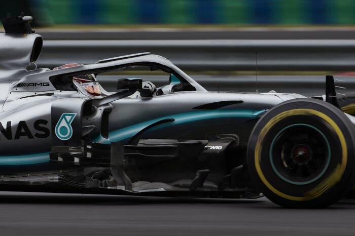
The current generation of Formula One cars are powered by high-performance downsized, turbocharged and electrified hybrid Power Units. This week, we’re looking at the mechanical heart of the PU, the Internal Combustion Engine and its development journey since 2014
What elements make up a Formula One Power Unit?
The FIA distinguishes between six elements in a modern F1 Power Unit (PU). At the very heart of the PU sits the Internal Combustion Engine (ICE). It’s a structural member of the car, connecting the chassis to the gearbox. The current F1 engines are six-cylinder engines, constructed in a V-configuration at 90 degrees, with a 1.6 litre displacement. The second element is the turbocharger (TC), which increases the density of the air that is consumed by the engine, thus giving the engine more power. A modern F1 engine is a hybrid engine, with two electric machines recovering and delivering energy. There’s the Motor Generator Unit-Kinetic (MGU-K), which harnesses kinetic energy when the car is braking, and the Motor Generator Unit-Heat (MGU-H), which is connected to the turbocharger and harnesses excess energy from the exhaust. Both motor generator units convert their respective energy sources into electrical energy which can then be used to propel the car. The electric energy is stored in the fifth element of the Power Unit – a big battery pack known as the Energy Store (ES). This intricate system of different components is controlled by the sixth and final element, the Control Electronics (CE). Drivers are permitted three ICE, MGU-H and TC and two ES, CE and MGU-K during the course of a season, but any combination of parts can be fitted to the car. If a driver exceeds this limit, they are given a grid penalty.
How does the combustion process work in an F1 ICE?
At the heart of the ICE is the combustion process where fuel and air are mixed and ignited to liberate energy. This process works in the same way it does on your road car; however, the systems are a bit more intricate. Looking at it in more detail, the combustion air is fed to the engine through an air duct that sits behind the roll hoop. The air pressure is increased by a compressor which is part of the turbocharger. This process also increases the air temperature, so the air needs to be cooled again in a charge cooler before it’s fed into the plenums at the top of the engine. From there, it passes down the six inlet ports and past two inlet valves into the cylinders. That’s where the fuel comes into effect. F1 engines are direct injection, like most modern road cars, so the fuel is injected directly into the combustion chamber. The fuel is injected at a maximum of 500 bar, which is limited by the regulations. While that is more than you would find on a direct-injection petrol engine in a road car, which usually sees pressures of up to 350 bar, it is actually quite a bit less than you might find in a modern diesel, where fuel pressures can reach up to 2,500 bar. The air and fuel mixture is compressed by the piston before a spark plug ignites it. The force of the combustion pushes down the piston, which is connected to the crankshaft through a connecting rod and is therefore able to drive the crankshaft. When the piston comes back up, the exhaust valves open to release the exhaust gases from the engine, so that the whole process can start all over again – up to a maximum of 15,000 times every minute (or up to 250 times a second). The exhaust gases are used to drive the turbine wheel of the turbocharger which in turn drives the compressor. What’s left then exits through the tailpipe at the rear of the car, with a wastegate system being used to control the pressure during this phase.
What other systems are part of the ICE?
Very intricate and complex oil and water systems are also featured in the engine, weaving between the different elements. These keep the engine running smoothly and regulate temperature, which is incredibly important when you consider that the gas temperatures in the combustion chamber can reach up to 2,600°C. The water system’s main job is to manage temperatures of the many different elements and materials that make up the F1 Power Unit. From the crank case, to the top of the cylinder head, it’s all about making sure the engine doesn’t overheat. A great deal of engineering goes into that, from managing the flow of water, to the pump efficiency.
What kind of gains has the team found since 2014?
The Power Unit regulations have remained fairly stable since they were introduced for the start of the 2014 season, so the general philosophy of the PU hasn’t deviated significantly from the original version that debuted five years ago. However, thanks to numerous changes in many areas, the team at Mercedes-AMG High Performance Powertrains in Brixworth has been able to improve every element of the Power Unit, producing more power and improving thermal efficiency. In 2014, the PU produced just over 900hp and had a thermal efficiency of 44%. That means that 44% of the energy in the fuel was converted into useful work to propel the car. Over the next years, the thermal efficiency was steadily improved, eventually breaking the 50% thermal efficiency barrier on the dyno in 2017.
Where did the team find more performance in the last years?
In the past five years, the team has looked at every single bit of the engine to find more performance and better efficiency. One area that the team did a lot of work on was the flow of gases in the engine – both in the form of the combustion air being fed into the engine and the exhaust gases coming out of it. In terms of the inlet system, one crucial area of development has been the plenums. They sit on top of the engine between the charge cooler and the inlet valves. The two plenums, one for each cylinder bank, hold pressurised air that is coming in from the compressor, providing a stable source of compressed air despite varying supply (owing to varying compressor speeds) and demand (an idling engine needs less air than one running at full throttle). From the plenums, the combustion air is fed through various inlet systems into the cylinders. The rules in 2014 demanded a fixed geometry system for the plenums, leaving little room for any performance gains. This rule changed for the following season, giving the engineers a new avenue to pursue. As a result, the plenums have not only increased in size, but also house a much more complex trumpet system. These trumpet-shaped ducts vary in length and thus match the tuned length to the engine speed and help to maximise the amount of air that is fed into the engine. In 2015, the trumpets turned into something that’s more like a trombone, where the inlet trumpet is sliding up and down on a port system, changing the length of the intake system with every move. This means the trumpet system and therefore the airflow can be adapted to the engine speed, providing the best length for different RPMs to produce the most power. Part of this evolution is even visible from the outside: since 2015, the plenums have increased in size every year, with carbon fibre extending the full length of the engine now and even pushing out the bodywork around the engine cover. This is why you can see small bumps on each side of the engine cover.
Did the team do any other work on the gas flow in the engine?
Another major area for improvement has been the exhaust system. Its shape, length and diameter have a massive impact on the performance of the engine, because the quicker the exhaust gases from the combustion process can be pushed out of the combustion chamber, the faster the new firing cycle can start. In 2014, the team used a lightweight exhaust system that was running the shortest possible route from the cylinder head to the turbine of the turbocharger. This system had two advantages – it didn’t add a lot of weight and the short pipes meant that there was not a lot of heat loss on the way to the turbine of the turbocharger and the MGU-H. However, the team introduced a more complex system in 2015 which helped to increase the power output of the engine. In this tuned exhaust, the primary pipes – the six pipes leading straight from the cylinder head – were the same length, but the secondary pipe was longer, thus altering the power curve and the power output of the engine. Since then, the team has introduced a new exhaust system every year, extracting more from the engine each time.
What other areas of the engine did the team focus on?
One other area where the team has made improvements is the materials we use. Large parts of the engine are metallic (for example, the cylinder head is made from aluminium) but the rules don’t always specific what metals must be used. Choosing the right alloys for the right components can impact both the reliability and the performance of the engine. Another area that the team is constantly working on is friction reduction. Friction takes power away – while the energy goes into heat rejection. This is where PETRONAS lubricants play an important role as the oil film between loaded components reduces friction and therefore increases power, but also reduces the wear and increases reliability. Getting the oil to and from the location in the engine where it is needed is also a development area. The engine is subjected to enormous G forces, it can experience up to four or five time the force of gravity when the car is braking, accelerating or thrown into a corner. Making sure the oil reaches every component that needs it but also getting it out of the engine again requires a very complex scavenging system. There are about ten oil pumps at the bottom of the engine, drawing oil from the cylinder head, the crankshaft, but also some of the ancillaries to make sure that the oil tank never runs dry.
What role does the fuel play in the hunt for performance?
The fuel is at the very heart of the combustion process and has a significant influence on the performance of the engine. The regulations state that the fuel needs to be unleaded, so it’s like the kind of fuel you would use in a road car. Does that mean you could potentially run an F1 Power Unit with regular road car petrol from your local filling station? You could – but it would require some changes to the calibration, for example to the ignition. You would also experience a very noticeable drop in performance. Why? Because the PETRONAS Primax fuel that the team uses has been developed over the last eight years and is minutely calibrated to work perfectly with the Mercedes Power Unit. A group of PETRONAS engineers is constantly working on the chemical composition of the fuel to make sure its characteristics match those required by the engine. This development work is done in close cooperation with the thermodynamic engineers at HPP.
How long does it take to build an F1 Power Unit and what is the process?
Power Units are complex machines and the more powerful they’ve become, the more complex they’ve grown. Back in 2014, it took a team of two people about two weeks to build an Power Unit. Fast forward to 2019 and the same task would take about three weeks with the same number of people. Therefore, the team at Brixworth had to try and condense that time so that it wouldn’t lose precious development time to the build process, and to do so, they added more people to the build process. So, two weeks has been maintained but with an additional person involved.
Stat Attack: Belgium and Beyond
|
2019 Belgian Grand Prix Timetable |
|||
|
Session |
Local Time (CEST) |
Brackley (BST) |
Stuttgart (CEST) |
|
Practice 1 Friday |
11:00-12:30 |
10:00-11:30 |
11:00-12:30 |
|
Practice 2 Friday |
15:00-16:30 |
14:00-15:30 |
15:00-16:30 |
|
Practice 3 Saturday |
12:00-13:00 |
11:00-12:00 |
12:00-13:00 |
|
Qualifying Saturday |
15:00-16:00 |
14:00-15:00 |
15:00-16:00 |
|
Race Sunday |
15:10-17:10 |
14:10-16:10 |
15:10-17:10 |
|
Race Records – Mercedes F1 at the Belgian Grand Prix |
|||||||
|
|
Starts |
Wins |
Podium Places |
Pole Positions |
Front Row Places |
Fastest Laps |
DNF |
|
Mercedes |
10 |
4 |
10 |
6 |
10 |
5 |
2 |
|
Lewis Hamilton |
12 |
3 |
7 |
5 |
8 |
2 |
4 |
|
Valtteri Bottas |
6 |
0 |
1 |
0 |
0 |
1 |
0 |
|
MB Power |
24 |
10 |
25 |
13 |
23 |
8 |
17 |
|
Technical Stats – Season to Date (Barcelona Pre-Season Test 1 to Present) |
|||||
|
|
Laps Completed |
Distance Covered (km) |
Corners Taken |
Gear Changes |
PETRONAS Fuel Injections |
|
Mercedes |
5,356 |
25,808 |
84,743 |
251,452 |
214,240,000 |
|
Lewis Hamilton |
2,567 |
12,376 |
40,715 |
120,773 |
102,680,000 |
|
Valtteri Bottas |
2,564 |
12,311 |
40,525 |
119,681 |
102,560,000 |
|
MB Power |
14,242 |
68,737 |
224,610 |
667,856 |
569,680,000 |
|
Mercedes-Benz in Formula One |
||||||||
|
|
Starts |
Wins |
Podium Places |
Pole Positions |
Front Row Places |
Fastest Laps |
1-2 Finishes |
Front Row Lockouts |
|
Mercedes (All Time) |
201 |
97 |
198 |
109 |
196 |
70 |
51 |
64 |
|
Mercedes (Since 2010) |
189 |
88 |
181 |
101 |
176 |
61 |
46 |
62 |
|
Lewis Hamilton |
240 |
80 |
143 |
87 |
141 |
43 |
N/A |
N/A |
|
Valtteri Bottas |
130 |
5 |
39 |
10 |
25 |
12 |
N/A |
N/A |
|
MB Power |
471 |
183 |
466 |
192 |
376 |
165 |
82 |
101 |
Source: Mercedes-Benz F1